 Indonesia
 Deutsch
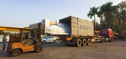
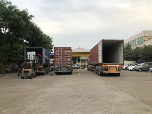
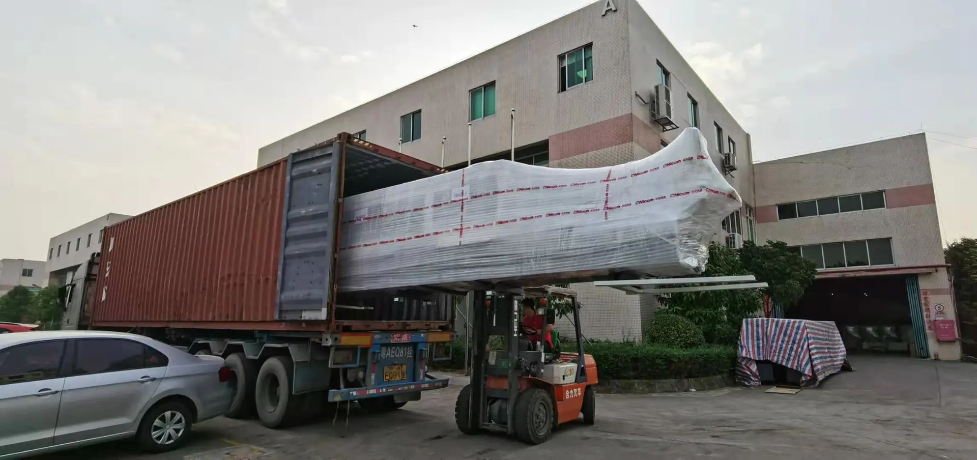
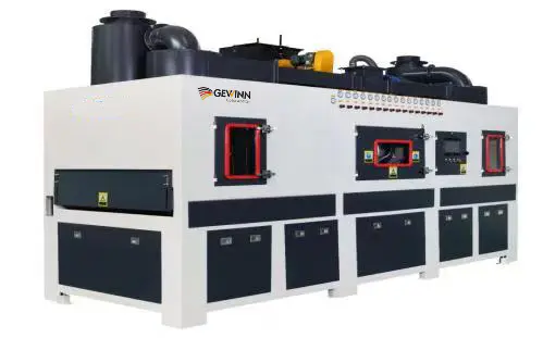
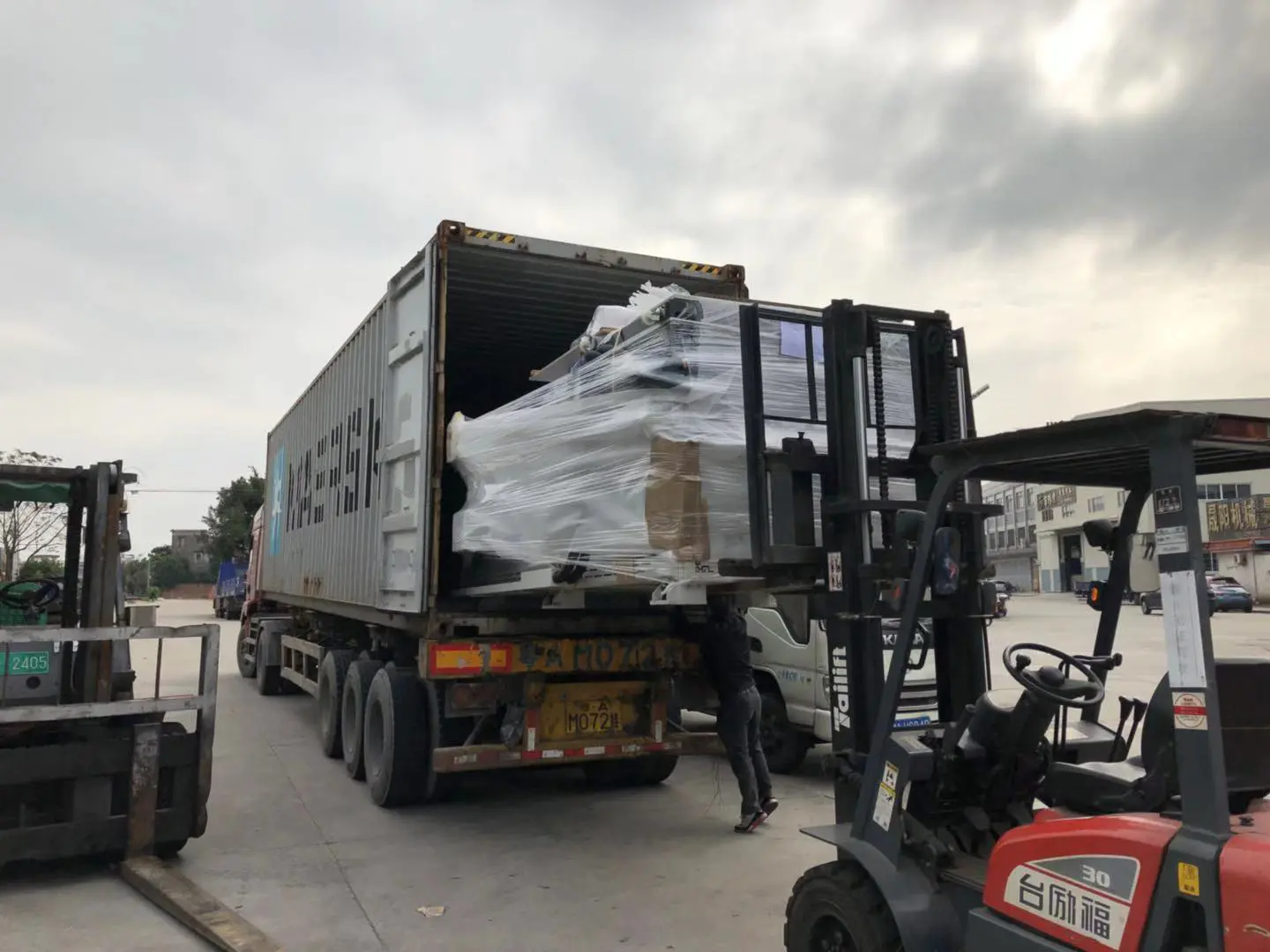
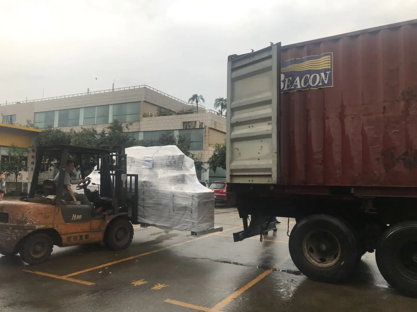
Shipment of CNC Machines
Products
diy adjustable belt sander
by:Gewinn
2020-06-04
Hello friends. . .
In this article, I will discuss how to make a DIY sander.
In fact, I never intended to do one, but this Sander is very important for my upcoming Layer Speaker project.
So I guess why not turn it into an article?
This is a very simple version of the Sander, but very useful and rigid in structure.
It can sand metal, wood, PVC and many other materials.
In addition, you can adjust the length between the two rollers with the help of the supplied bolts, which allows the Sander to adjust to all belt lengths, making it more versatile in all applications.
One of the rollers (driver roller)
By connecting the long bolts of the second roller to the rig (driven roller)
Rotate when Belt sand is placed on top.
It\'s better to watch the video first and then read the article to get the whole picture.
Let\'s discuss the build now. . .
The Wooden Roller is the most important part of the Sander because the belt is spinning on this roller.
We need two of these rollers to make a conveyor belt drive system.
The rollers are made of round parts of plywood, which are fixed one by one using brad nails to form a stack of plywood and eventually form a roller.
These circular sections are cut using a standard hole saw of 44mm connected to the rig.
The number of round sections required will depend on the thickness of the plywood section and the width of the belt.
I only used 12mm plywood parts throughout the project.
The sand belt I use is 10 cm wide, so the 9 round sections cut from the 12mm plywood are enough to accommodate the sand belt.
Since we need two of these rollers, we need 18 round sections in total.
When we make a circular section using a hole saw, if we fix the drill bit on the hole saw attachment, the central hole has been created.
This center hole for each part can be used to drive the roller through the center shaft.
The shaft I am referring to is just a long bolt, about 4 cm longer than the roller length in order to accommodate additional support blocks at both ends of the roller.
After cutting 18 parts, its time becomes a roller.
In order to achieve perfect alignment, it is best to insert the bolt into one of the round sections first, and then place the second section on the top of the first through the bolt.
For extra strength, you can also apply some wood glue between these parts.
After placing the second part at the top of the first, fix the two using two to four brad nails.
Again, repeat the process to form 2 rollers consisting of 8 parts.
After completion, if there are still minor defects on the surface, then we can attach these rollers to the rig, rotate on the surface and place a piece of sandpaper, this way we can make the surface uniform and smooth, which is very important for the smooth operation of the belt on the roller.
The bracket holds the roller in place and keeps the gap with the bottom platform, arranging everything on the bottom platform.
This clearance is critical for easy insertion and movement of the belt.
Since we have two rollers, there should obviously also be two, one of which is fixed and the other is removable.
The two holders are exactly the same during construction.
The bracket is made of 3 pieces of plywood, the small two pieces act as the final support, and there is a longer piece at the bottom that fixes the two side pieces vertically.
The side blocks are drilled on the flat side, ensuring that the holes in the two blocks are placed exactly at the same vertical distance.
This is the hole where we place the bolt containing the roller is fixed.
The structure is done by piercing some brad nails from the bottom block to the side block placed vertically above the bottom block.
You should get an up C structure when you\'re done.
One important thing to note is that after fixing the first block, don\'t forget to be 2 cm longer than the horizontal roller length, because we fix the roller after fixing the two end blocks.
Please also make sure that you have provided enough vertical clearance for roller free rolling and belt rotation on it.
In my opinion, both can pass.
The work will be done by 5 cm or 2 cm people.
This completes the first bracket.
The second roller I. e.
The moving rollers are the same as above, but a little different.
The bottom plywood block is a little wider than the roller.
The idea is to slide the entire component consisting of 3 blocks and rollers on the final platform through the slit provided on the platform.
The two bolts are inserted into the slot of the bottom block, then through the slit of the bottom platform and can slide the entire assembly through the slit.
After fixing a convenient position, the bolt can be tightened with the help of the nut.
Also, make sure that the Bolt is inserted into the head at the bottom of the platform and through the C-bracket so that we can tighten the bracket from the top.
Both holders are completed.
The basic platform is the platform to install all the arrangements.
The size of the platform depends on the size of the rig and the maximum length of the belt that the installer can use.
In my personal opinion, the use of a belt of more than 1 m in length is a bit on the higher side.
I will tell you why, because no matter how hard you try, the belt is only supported on two rollers, and the belt will be a little loose as the length of the belt increases.
This creates a weak point where grinding in the middle part of the belt can dent the belt slightly, thus bending the desired surface instead of a completely flat surface.
So what I\'m trying to say is, assuming we\'re tied to the sand, then using a shorter length belt can be of great benefit to the surface finish.
So if we have a limited maximum length belt, 1 m then we need a roller of at least 1 m, the roller distance, because when the belt is installed around the roller, the half span of the total length of the belt is obtained, and the roller is above and below half a meter to form a single belt.
Therefore, in order to shorten the basic platform length of more than half a meter, such as 70 cm.
When the width of the bottom plate is a little longer than the horizontal length of the rig.
I am using the Bosch GSB 600 RE With a length of 26 cm so to make up for this I used 30 cm as the width of the substrate.
After cutting the base platform to the required size, it is time to repair the drive roller.
This is the roller directly connected to the rig.
Therefore, it must be fixed directly and correctly.
I fixed the roller and support system to the base platform with some brad nails.
After fixing this Roller, keep the two slots perpendicular to the roller firmly on the distance.
Cut on the base platform.
This is the bolt inserted that will hold the second movable roller.
As we discussed in the above-mentioned meeting, the rig that powers the roller (driver roller)
And rotate it on the shaft supported by the end plywood block.
Since we are tightly attached to the belt around the drive roller and the second roller (driven roller)
It forms a belt drive system, thus rotating the second roller through rolling motion and friction of the belt.
Therefore, we can carry out polishing operation on the continuous rotating belt.
The main thing to do next is to repair the rig.
I \'ve seen several tutorial videos where drilling machines are not supported at all and are not fixed on the platform.
This can be very dangerous if we apply a higher sanding force to the belt, which is often needed to polish the wood block or something of a larger size and quality.
The reason is that when we apply resistance on the belt in the sanding operation, this is contrary to the rotation force of the rig, so a reverse torque is developed to try to rotate the entire rig.
When polishing smaller mass objects at a lower speed, this will not be very important.
However, if the rolling speed and quality of the desired object are relatively high, we should limit the movement of the rig by correctly creating a locking mechanism for the machine, which will be discussed in the meeting below.
The movement of the restricted rig does not have a specific arrangement for fixing the rig in place.
The only thing to consider is that once the bit is attached to the Bolt of the drive roller, the bit should be completely straight and all freedom of movement of the rig should be limited.
After collecting some small pieces of plywood, try to insert where the rig needs some support.
I will discuss what I have done for support.
After tightening the bolts onto the rig Chuck, I started aligning the rig to the bolt, which provided very smooth conditions for the uniform operation of the rollers.
The height of the drill machine is matched by inserting the plywood block into place.
Just before the rotary axis of the rig, there should be a circular extension to support the shaft.
The round part is a perfect start.
Try inserting blocks under this circular cross section to align the stand and drill bit straight.
Then go there and find the handle of the rig, where you can install a removable stand to constrain the backward movement.
For removable brackets, you can make a rail track with two rows of plywood, one row stacked on the top of the other so that the other row of plywood can be mounted on the width.
First, insert and fix the rig with this removable plywood.
An angular structure was also created at the trigger of the rig.
After installing the rig, mark the position of the trigger and fix the nut in the position of the trigger so that when the bolt is inserted and turned forward, the speed drilling machine of the trigger can be adjusted.
A separate picture of this component is added to this session.
So it\'s almost done.
The last thing is to fix the belt between the rollers.
For this, the belt should be continuous, we used some interior decoration resin and cloth on the back of the belt (i. e.
Non-grinding side)
Form a single belt.
One thing to note is that when the two ends of the belt are glued together, they should be cut in a way that skews the cutting position interlocking.
This is done by placing both ends at the top of the other end and then cutting out a tilted part from the edge.
Then fold two edges in the reverse I. e.
Wear side up.
Use the interior decoration glue and the cloth on the back to connect the two equal and opposite parts.
The reason for this is to apply the force acting on the joint to a larger section, and if this tilting cut is not provided, then the full force on the belt will be applied to an action line, so that the part is more prone to failure.
After gluing the belt with adhesive, place some weight (i used brick)
At the top of the connection section, this strengthens the bonding, so we can get a perfect continuous band without interruption or projection.
So once everything is done, we can start running the belt by powering the rig and slowly turning the bolt to control the trigger speed.
If our job requires a higher pressure on the belt, then we can do this by polishing it on the roller, like I did when I was polishing the rusty metal knife, the introduction of my video.
I was impressed when I saw the results, which was higher than I expected.
Shiny Knife after polishing is the best example.
It also works well on wood.
As I mentioned before, the Sander is actually used to polish the wood and it works very well.
So this is the guys. .
Please let me know your thoughts and suggestions in the comments section below.
Thank you for reading this article patiently.
Custom message
Related Products