 Indonesia
 Deutsch
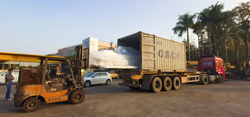
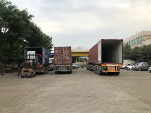
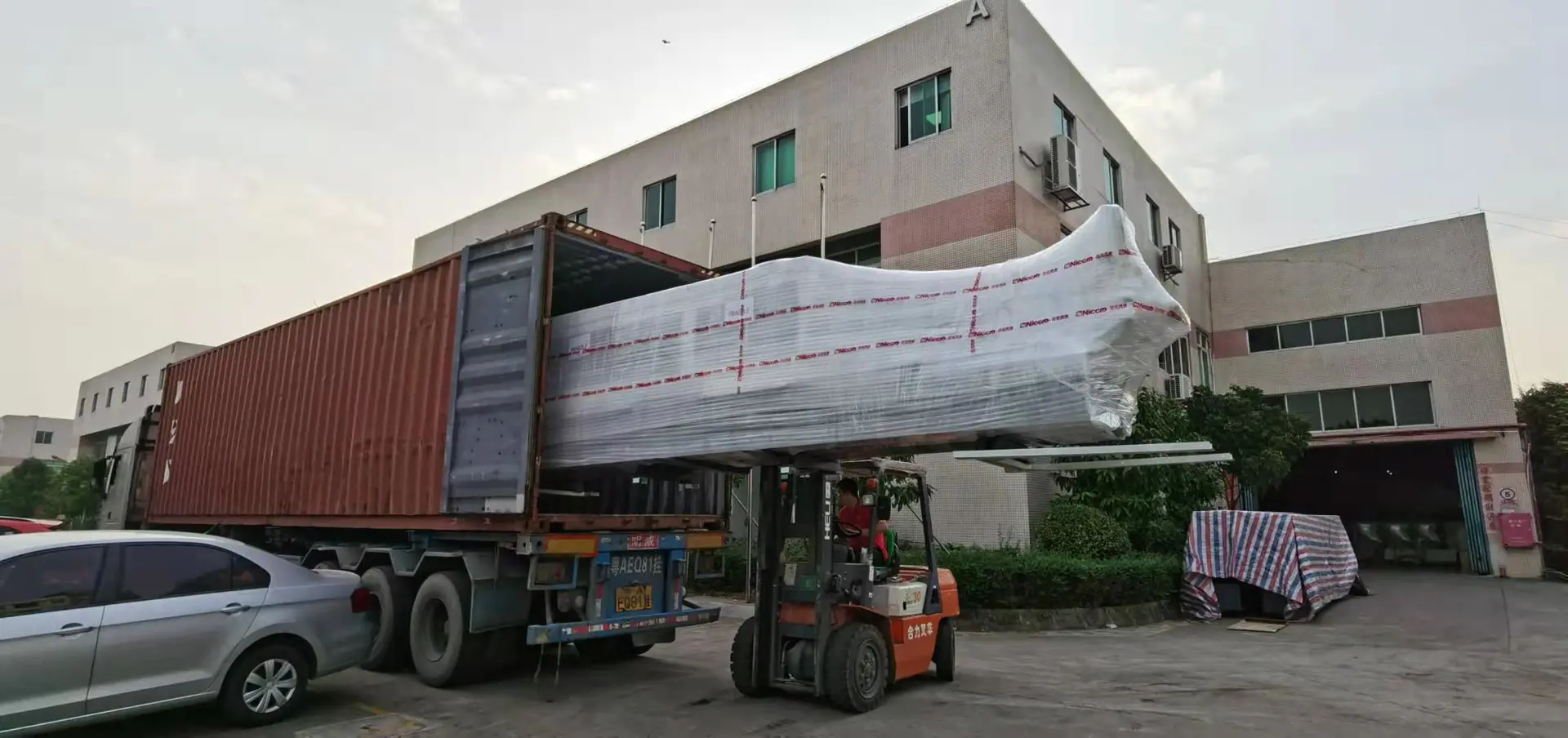
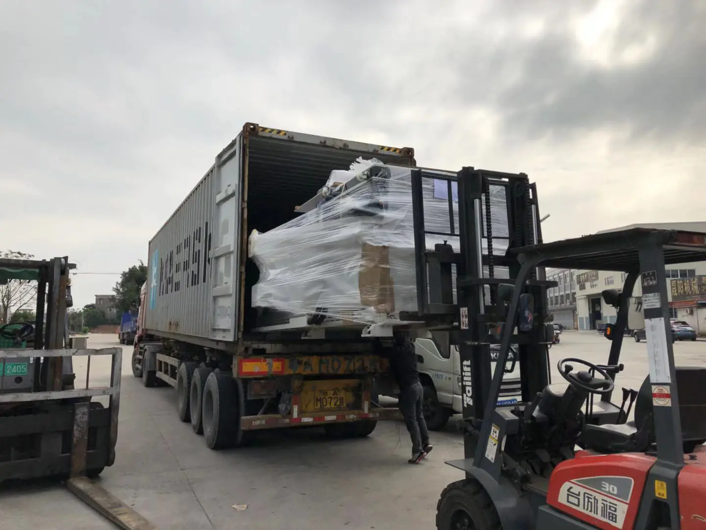
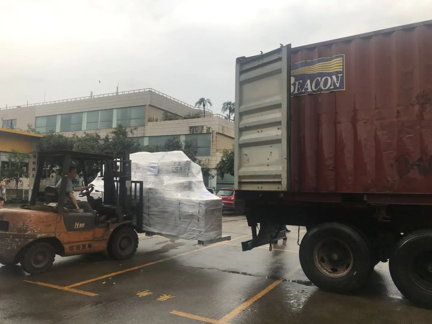
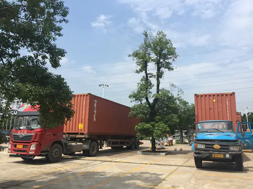
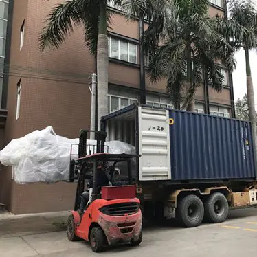
Shipment of CNC Machines
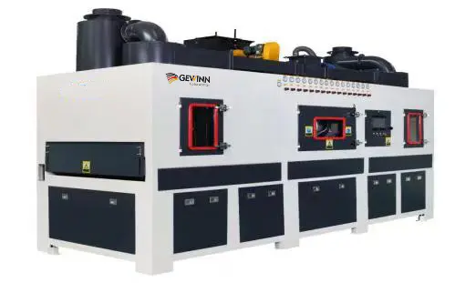
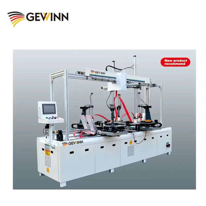
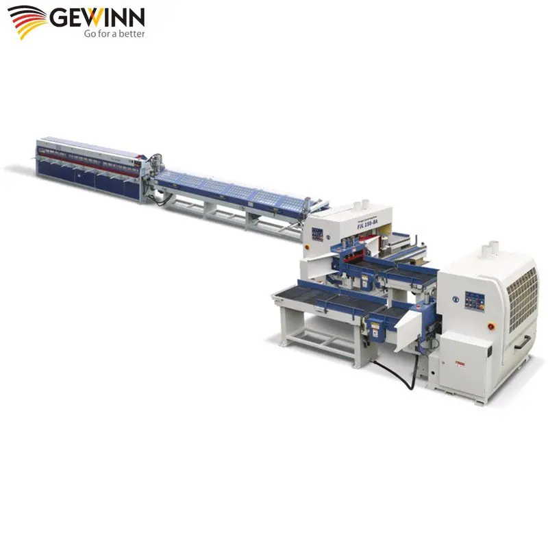
Products
drawing custom toolpaths for cnc milling (to create your own surfaces)
by:Gewinn
2020-06-07
Whether the goal is aesthetic or efficient features, the potential of CNC milling machines to create patterns, reliefs, textures, and complex surfaces is fascinating.
The CAM program allows us to take advantage of many automatically
Generated toolpath (
The path through space that the tool tip follows in the process of generating the required geometry of the workpiece).
However, if you want to have full control of the surface you are working on, you need to draw your own toolpath.
Often, the goal of machining is to achieve as smooth a surface as possible while machining, as this will be the result of the CAD model closest to them.
However, this high
Resolution processing usually takes a long time because a small stepover is needed. Low-
Resolution processing with large stepover is much faster, but pre-
Programming the toolpath does not always leave an ideal pattern or surface.
When using pre-
The programming toolpath found in the CAM software, the final surface pattern will always be recognizable, default, and predictable.
By drawing your own toolpath, you can get the desired surface pattern exactly.
By being able to implement the pattern you want, you can usually reduce the smoothness to get a more unique, interesting, and efficient surface of the result.
I have studied this technology from the perspective of architectural aesthetics, in recent projects such as daylight research, daylight modules, capture light research, etc.
But there are a lot of other potential apps!
Use the CAD program of your choice (
I used Inventor and Fusion 360 in this example)
, Build a 3D model of the surface or object you will be working on.
The 2D pattern will be affected by the shape it projects to, and the final result will be a combination of the 3D shape and the 2D pattern.
I would suggest starting with a simple form, such as a plane or a subtle curve, so that you can study the effect of the resulting pattern more easily.
There are many different techniques for creating 2D patterns as tool paths.
Drawing size-
Constraint line system in Fusion 360, using parameter software to generate patterns (
Such as the grasshopper Rhinoceros3D of CorelDraw of SecuriDesign)
, Create a complement between the two curves in Rhinoceros 3D, scan the hand-
The pattern drawn, and convert it to a vector using Illustrator, etc.
It all depends on the effect of your goal.
For example, I \'ve been working on patterns that create visual illusions that allow viewers to \"see what they see\", so I \'ve been using repeated line gradients, overlapping patterns that produce more effects by interference and other types of subtle optical patterns.
The distance between lines or points is the most important aspect of the pattern, as it is stepover, or the distance between each passing through the vertical mill.
The larger the Stepover distance, the more stock material between the channels, forming a deeper relief.
In addition, the larger the stepover, the shorter the processing time, because there will be fewer passes to complete the operation.
One of the benefits of drawing your own toolpath is the ability to create different stepover.
Make sure the 2D pattern is aligned correctly with the 3D model, especially when importing the pattern from other software.
When creating a projected toolpath in Fusion 360 or Rhinoceros3D, your pattern does not need to be directly on the surface of the model, but can be \"floating\" directly above or below the model \".
You may want to extend the lines of the projected toolpath slightly beyond the edge of the model (
By half the diameter of the vertical mill)
To ensure that the tool clears the edges of the model every time it passes through.
The vertical mill you select for customizing the toolpath will determine the generated surface.
For example, a flat vertical mill will create a step Terrace, a ball
The head vertical mill will produce a circular groove with a sharp ridge between 45 V-
Groove vertical grinding will create a triangular face.
You should also consider the size of the part you are working on and consider the appropriate diameter of the vertical mill.
For example, if you are going to process 4 \'x8\' foam sheets, it will take a long time for a 1/2 vertical mill to process the pattern to the entire surface, and it is difficult to see the pattern from a distance, so in this case you might want to use a larger pattern like a vertical mill with a diameter of 2.
Most CAM software has the option of using custom vector lines as the toolpath for machining 3D models.
In Fusion 360, this option is 3-
Shaft machining options.
In Rhinoceros3D, the same function is named \"curve machining \".
Fusion360 is now full of 5-
The axis option for this operation, called multiple
Axis profile, where the tip of the end mill remains normal to the surface of the model throughout the tool path.
Enter the end mill information, select the lines of the 2D pattern for the tool path geometry, select the 3D model as the surface to be machined, and generate the tool path.
The cutting line of the toolpath should now be projected onto the surface of the model.
Depending on the material you are going to process, you may need to perform a rough machining operation to remove the additional material before proceeding with the custom toolpath.
Alternatively, you can process custom toolpaths in multiple stepsdowns.
If you are working on soft materials such as low density foam, you don\'t even need to use a rough machining operation in advance.
Run simulation in CAM software.
This is the only time you can preview a combination of custom 2D toolpaths, 3D models, and selected vertical grinding before machining.
Look at your simulation carefully.
Are you satisfied with the results?
If not, please make the necessary changes and simulate again.
The iterative simulation process helps develop the design before machining and saves processing time.
Check for collision or over Simulation
Aggressive passing
There are more opportunities for these situations in the custom toolpath, so watch the simulation carefully.
Once you\'re happy with your simulation, customize the toolpath!
This will be the first time you \'ve seen your toolpath implementation, so expect to be surprised by the results, and don\'t expect it to show up as you think.
One of the pleasures of CNC machining is to achieve and compare the differences between 3D models and the machined objects.
Although there is a lot of preparation and planning for CAM programming, in real-world conditions, there is a lot of room for the conversion from 3D visualization to physical materials to produce unexpected results.
Take a closer look at your results, reflect on what works and what doesn\'t, and then proceed to the next iteration!
This structure is just the first source of inspiration to try new technologies.
There are countless potential changes and applications to this technology, and I am happy to see any work that may be inspired by this technology!
Two specific projects on instructures can be inspiring or helpful in developing your own toolpaths, especially the aluminum toolpaths, which are Machine inscriptions from Matt Hutchinson and Julie
Custom message
Related Products