 Indonesia
 Deutsch
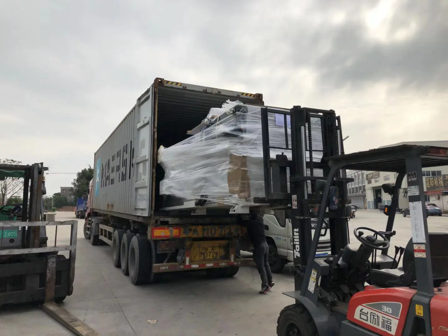
Shipment of CNC Machines
Products
how to build the sienci mill one desktop cnc
by:Gewinn
2020-06-06
Introduction desktop CNC machine tools are the perfect tool for manufacturing small and medium parts and projects from virtually unlimited materials.
Designed for simplicity and ease of use, Sienci Mill One requires only the least amount of components, and its price range and grade provide the highest level of performance and rigidity compared to other machines.
While factory manufacturing will benefit from the use of industrial manufacturing methods to make ready-to-buy kits, factory manufacturing can use tools that most people can use.
Most of the components used in the factory can be purchased online or in the nearest hardware store.
Parts like coupler, screws, stepping motors and drives can all be found as 3D printer components, and over the past few years 3D printer components have become more popular and cheaper.
You may even have these parts on hand!
Fasteners, aluminum or steel are all based on standardized dimensions and can be found in hardware stores.
If it is difficult for you to find the right parts and materials, this manual will give you some advice on how to find the right replacement.
The design of factory 1 is open to everyone.
You can find the latest design on onform, and you can find the old design file on Github.
Please see the mods example on our Facebook user group.
You can modify the design to suit the material at hand, or you can modify the design to suit your needs.
Some files may be out of date and some designs may change over time, so feel free to let us know if you find any problems.
Some of the holes in the mill need tools that are precisely drilled.
It is recommended to use a milling machine or CNC to complete this task, you can find one in the local makerspace, but you should be able to make this machine with a drill bit, ruler, a careful and stable hand.
A saw suitable for cutting 1/4 aluminum or steel is required.
Just a hacksaw.
Router for cutting some holes on the frame.
In any case you should get a router to act as the mill spindle.
Here is a short guide on the use of routers with regular routers.
A 3D printer is also needed to make some parts.
This machine uses about 500 grams of filament and it takes 18 to 20 hours to print (
Depending on your settings).
A set of metric Allen keys is required for assembly.
The bill of materials and the full suite can be found in our store: the bill of materials can be found here: view the BOM for the latest list of parts.
About UsSienci Labs is an established company whose vision is to bring simple, low-cost automated manufacturing tools and rapid prototyping technology to everyone.
In the second year of mechanical engineering at the University of Waterloo, we designed and developed different low-cost linear motion systems.
Learn more about what you would like to support us or prefer to have us make a factory kit for you and you can order a full factory kit for $399 on our website.
Like we do on facebook, follow us on twitter disclaimer, and while we do our best to provide the latest and accurate information possible, we are not responsible for your project and security.
Specifications and other documentation on our website may not be reflected in your own build, nor can we guarantee the performance of your machine.
Some short notes: Here are the mill room specifications posted on our website.
Depending on your configuration, your specifications may vary.
Model: 1 working area of the mill: about 235mm x 185mm x 100mm (
9 \"x 7\" x 4 \")
Machine Volume: about 430mm x 300mm (
17 \"x 11 \")
Mechanical resolution: 0.
Maximum travel speed at 1mm micro-step: 1200/min (arbitrary cap)
Command to the controller: G-
Code Drive System: CNC v3.
Arduino Uno of the shield of the month A4988 HCARDU0086 Arduino with Pololu stepping motor driver and GRBL firmwareSoftware compatibility: Universal g code send, Kiri: Moto, Fusion 360
Send plugin with generic GCode)
And other g-
Code sending software (
Some 3D printer senders work)
Interface: usb power supply: external 120 V/220 V, 50/60Hz AC to 24VDC 5 power consumption: 110 W (max)
Running speed: the recommended speed depends on the tool selection and the hardness of the material.
Lists some of the typical feed speeds and cutting depths of the machines we use 2-slot end \"Vertical Grinding.
Wood: feeding rate: 800 to 1200mm/minute cut depth: 1.
5 to 2mm 6061 aluminum: feed rate: 800 to 1200mm/min cutting depth: 0. 08 to 0.
1mm coolant: water or rubbing alcohol acrylic: feeding speed: 500 to 1000mm/minimum cutting depth: 1 to 1.
5mm PVC: feeding speed: 800 to 1200 cutting depth: 1.
Material diversity from 5mm to 2mm: metal is softer than aluminum, wood, plastic, foam, printed circuit board, leather, etc!
The Tibetan GantryThe Tibetan gantry can be made of any hard 1/4 to 3/8 plate.
The aluminum or steel works well and the plastic is often soft enough to limit the performance of the plant.
If you are only going to grind wood and other soft materials, you may be able to use plastics such as acrylic, PVC or high density polyethylene, but it is highly recommended to upgrade to metal.
Tools like manual grinding are great for drilling. For 7.
The 12mm hole, the 9/32 bit will provide the perfect fit for the hole of the eccentric nut.
If you do not enter the mill or CNC milling machine, you should be able to make one with a drill bit and a stable hand.
Depending on the size of the angle aluminum, you may need to change \"89 \".
75mm \"hole distance if you find that the v wheel is too loose or too tight even after adjusting the eccentric nut of the v wheel.
The eccentric nut is the nut that offsets the threaded hole from the center.
This allows the NUT to rotate to adjust the position of the v wheel.
The V-wheel must be positioned correctly to allow a proper amount of pre-load between the on-orbit and v-wheel, and the eccentric nut allows to adjust the pre-load.
You can use standard M5 eccentric nuts, or you can use our custom eccentric nuts, which have longer holes and are suitable for Gans with a thickness of more than 1/4.
You can find them here: the Y axis gantry is made of 1/2 \"HDPE due to its durability, but it is soft enough to accidentally fall into the bed with a drill bit or vertical mill, it will not damage the machine.
We also used 1/2 PVC in the past and it worked very well.
If you have a CNC router or milling machine, you can easily make your own Y axis gantry.
Below is a video of a new bed carved from PVC for Mill one.
No, you can drill the proper holes and add drill bits to allow enough space to tighten the nuts of other sizes.
You can also use a 1/4 piece of material at the bottom of 5mm and 7.
Keep the 12mm holes of the v wheel, and there are 1/4 \"layers on the top to ensure the working face is flush.
As mentioned by Tibet gantries, use 9/32 or 7.
The 14mm drill bit will provide a good fit for the eccentric nut.
The linear track system of mill 1 uses extruded 2 inch wide 6061 or 6063 angle aluminum, which provides two \"v\" edges that allow v-wheels to operate.
The x-axis and y-axis use 400mm rails, and the z-axis uses 200mm rails.
In order for the v wheel to work properly, you need to make sure that you are using the holes in the track and can also drill and dig on the mill, but if you do not have the right M8 tap, can use 8mm of the hole.
When you assemble the rolling mill, fix the bracket and angle aluminum together using longer bolts and nuts, but make sure there is enough space for the motor coupler.
These parts are 3D printed and can be printed on almost any 3D printer and can be printed with ABS or PLA.
Here is the estimated printing time for each part, 0.
The 5mm nozzle on Marriott i3 is at 0.
3mm floor height.
Each component is designed to be printable without support.
We often modify our design in order to find the latest 3D model, go to onform, and then navigate from the home folder to parts> 3D printed parts \".
Select the design you need and right-click the model.
Press export to select the 3D model (Typical STL)
For the 3D printer slicer, you want to export.
The old design can be found on Thingiverse: a quick note that the frame holder used on the mill is laser cut-formed steel, not a 3D printed part.
The frame holder for 3D printing is thicker and provides more rigidity, but can be modified if needed.
For nut stand, Angle stand, router stand and frame stand, use high fill (80% and above)
Thick Shell (1. 5mm or more).
The electronic chassis does not require much padding and can be printed with 20% padding.
The total amount of filament used for each set of 3D printed parts is about 500g PLA, but may vary depending on the 3D printing settings.
There are many uses for the frame in the factory, which is a barrier to lost hands and an easy way to manage dust and structural support.
We chose to use the 1/2 medium fiber board because it is cheap and the size is stable (in non-
Wet environment, stable temperature)
And the source is quite easy.
To put it simply, we are using a premium grade mid-fiber board that is superior to the standard grade mid-fiber board commonly used in the building, and you may need to go to a local supplier to find it.
That is to say, in addition to the medium fiber board, you can also use a lot of suitable plates.
You need something that is stable in size as it does not significantly change the shape due to changes in temperature, humidity and other factors and is still reasonable.
Metal like aluminum or steel is very good, but it will be very heavy if used for the mill frame.
High density polyethylene and PVC are easy-to-use plastics with good results.
If you can use a laser cutter, you can even make your frame with acrylic resin.
In fact, we made some prototypes by layering two pieces of laser cut acrylic.
It\'s really expensive, but it looks great, and you can look right in the past.
The CNC router is very convenient to make the frame, but not everyone has such a router.
We found a group of people locally and they did have someone who made the frame for us at a reasonable price.
The enclosed DXF is the latest frame design you can use to make the frame, and you can use it to modify the frame size if you want to make a bigger or smaller mill.
If you do not have access to the CNC router, you can also drill and wire manually.
As long as the holes are in the right position and the frame is cut straight, you should get a square machine.
If you are not confident in your drilling technique, please add a slightly larger hole size so you can loosen and re-adjust your machine until it is true.
The handle and hole of the motor can be done using a handheld router.
As long as the holes are large enough to hold the motor or your hands, they are not critical in size.
Use acrylic ShieldA clear, 3mm thick acrylic or polycarbonate shield at the front of factory 1 to provide additional safety protection and help keep the dust inside the machine.
The size required for this panel is about 422. 7mm x 200mm.
You can see cutting it or laser cutting these plates.
Laser cutting does leave a better edge, giving you the chance to carve on the material, but it works really well using a saw.
Arduino Uno and CNC v3 control electronics.
Shield is easy to get online and very cheap.
The A4988 stepping driver chip is also easy to obtain and is commonly used in 3D printers.
The DRV8825 is also available, however, it is recommended that you use the fan cooling drivers as they tend to run hotter than the A4988 drivers.
You can also use most 3D printer control boards (
We used a ramp.
4 and MKS basis for past testing)
, Or other CNC control boards such as gshield or grblshield, if you have them on hand, or prefer to buy different control boards.
You will need 17 stepping motors for three film associations. We use 1.
5A motor of 40Ncm/57. 1oz.
In holding torque, keep the torque working well and provide enough torque to drive the shaft, but not enough to damage the machine when it crashes.
Anything smaller than this has the potential to turn off, so go and find the largest compact 17 motor you can find/afford.
This compact 17 motor comes with a detachable 50 cm cable that is long enough to reach all three axes from the control box.
Make sure the cable is long enough when you buy the stepping motor.
The power supply standard mill one kit comes with a 24 v 5A enclosed power supply.
Some people call it brick \".
When selecting the right power supply, the rated current of the three motors should be added (In this case, 1. 5A + 1. 5A + 1. 5 = 4. 5A)
And get a power supply that can output at least that current.
It\'s good to have some space, especially if you plan to upgrade your motor or drive.
The power supply has various voltages such as 12 V, 24 V, 36 V or 48 V.
There is a working voltage range for each control board and drive, and the A4988 drive is typically 8 v to 35 v, 8.
2 v to 48 v with drv8825.
We recommend the use of the highest voltage, as the higher voltage will allow the stepping motor to operate at a higher speed due to the design of the motor.
The power supply has various shapes and sizes, some are closed, some are metal boxes, which are very porous and used for ventilation.
We like to use closed power supplies because they do not touch the supply voltage and are not affected by dust.
However, you can use any power supply of the right specifications you want.
The ladder lead screw and nutsYou need a set of motors with nuts, coupler and transmission power.
These parts can be purchased online.
Here are some details about these items and you need two screws of 400mm and one of 200mm and their corresponding ACME nut.
We use stainless steel ACME screws with a diameter of 8mm, a starting time of 4mm, and a spacing of 2mm.
This type of screw is usually used for 3D printing, usually on the z axis.
There are several types of ACME nuts, but compatible with the rolling mill is the most common one that can be installed in a 3D printed ACME nut holder.
What has recently become more popular is the spring-loaded anti-bounce nut, which helps to eliminate some bounces, which can also partially lower the standard ACME nut.
Coupler you need a coupler to connect the lead screw to the motor shaft.
The month-to-month model has a 5mm axis, so be sure to find a connector that fits both the lead screw and the motor shaft.
If a screw with a diameter of 8mm is used, use a coupler with a diameter of 5mm to 8mm.
The aluminum coupler like the blue in the photo is quite cheap and uses a lot in the 3D printer, but you can also find great steel coupler.
In short, since screws are not supported, you cannot use a flexible shaft coupler.
The Flexible Shaft Coupler will stretch back and forth parallel to the shaft and screw, which will result in inaccuracy.
If you really want to use a flexible shaft coupler, you have to support the screws on the other end with the bearing and collar.
If you do not want to use the ACME screw but prefer to use the screw bar, then one step of the replacement is to use the M8 screw bar and the M8 nut.
You will need to create a modified nut holder to secure the M8 nut.
You can even make your own coupler fairly easily by taking a piece of stock material, drilling a 5mm hole in the whole material, and drilling a 8mm second hole in the middle of the material, then drill and tap some fixing screws on the side of the stock to maintain the position of the shaft and screws.
We have done this before and found that things are easily misaligned, causing the screw and motor shaft to fall-
Center, so you take the risk yourself.
Mill one is very easy to assemble, and it usually takes 2 to 3 hours to assemble for an inexperienced builder.
Experienced people and electric drills can assemble one in about an hour.
We have created assembly videos on Youtube that you can follow: or go to our resource page and find our PDF instruction manual.
We hope you find this instruction helpful and informative.
Seeing people, especially those who have never used CNC machines, turning their 3D designs from materials such as wood, plastic, foam into real objects is exciting for us, and the use of metal grinding. Have questions?
We have a Facebook user group here: there are a lot of great people who can help you.
You can also contact us via email from hi @ sienci. com! Happy building!
Custom message
Related Products