 Indonesia
 Deutsch
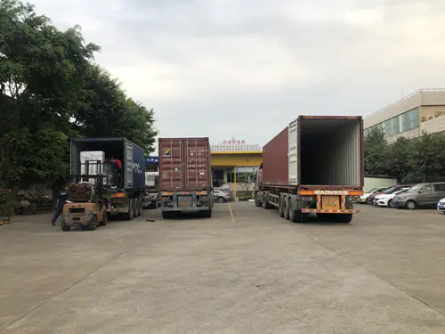
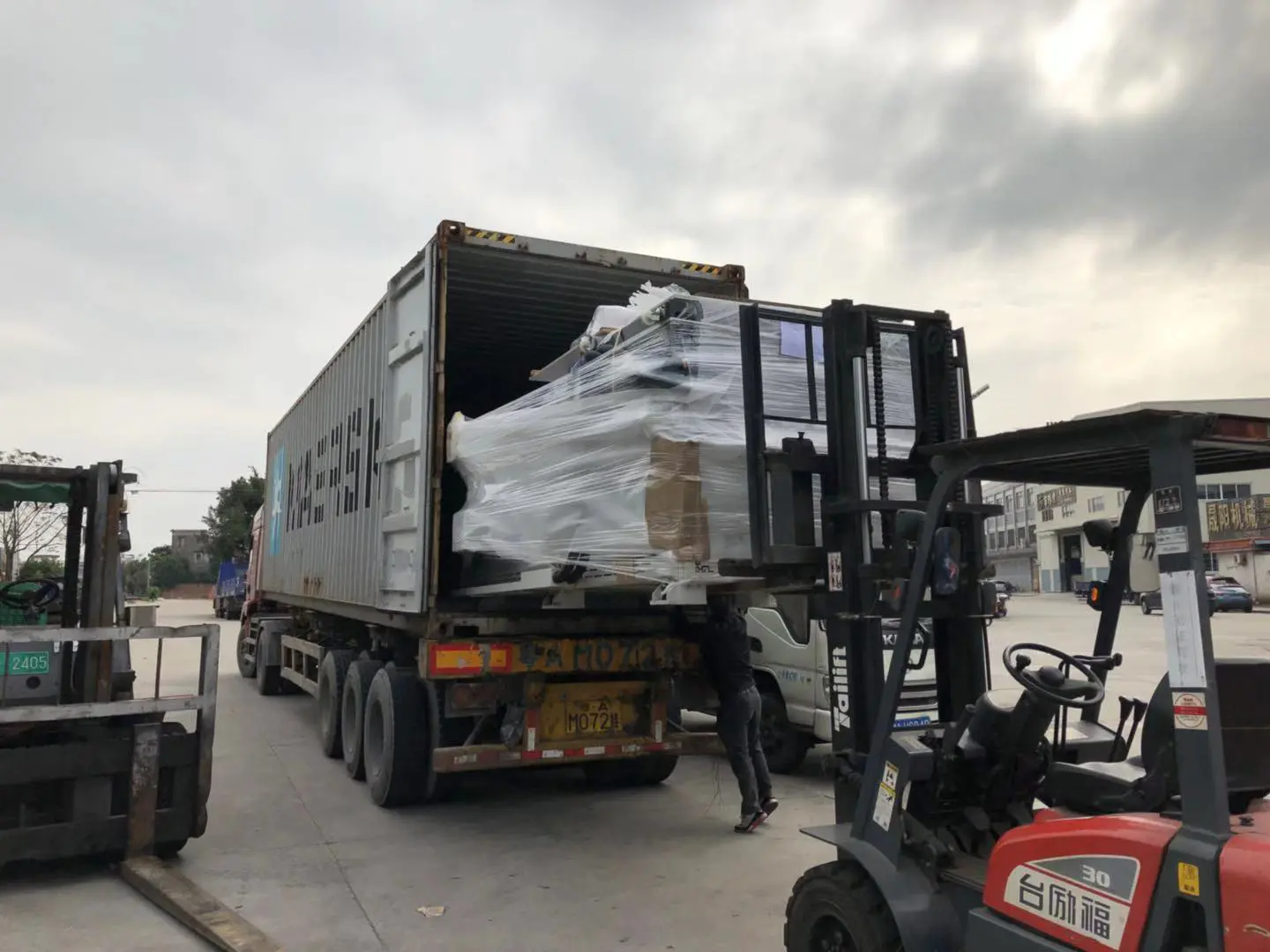
Shipment of CNC Machines
Products
lash out! - how to make a milling machine more accurate
by:Gewinn
2020-06-15
Play well, but not on the milling machine.
Nothing is more frustrating than working on a milling machine, but playing too much on the handwheel is almost impossible to do accurate work.
Play with the hand wheel called \"lash \".
In this structure, I use the Sherline 5400 grinder to demonstrate how to remove the lashes completely.
I will provide a basic overview of disassembly and reassembly including adjustment and calibration of zero point
Precision clearance milling on the Sherline 5400 milling machine, which can also be easily applied to other small machines.
The accuracy of Sherline is 4 digits after the decimal point (0. 0001\")
Make it a powerful tool with the right adjustments
Just adjust correctly.
If you are interested in converting an existing milling machine or lathe to CNC, eliminating the gap is also the first and most important step, and CNC requires zero clearance.
When I purchased my product, both the lathe and the milling machine were covered with a thin layer of rust and were completely unusable due to serious maladjustment.
I used these machines in this case because many small metal processing machines were used and then I realized it might be better.
Here\'s what I \'ve done to make it a clearance-free full-precision mill again: Step 1.
0: remove the carriage sliding gasket by loosening the small fixing screws on the side of the carriage.
Use the small inclined slotted screwdriver to gently pry the loose gasket fixing pin and be careful not to remove the sliding gasket before March.
This will slide the gasket and the fixing pin out of the groove.
For those who are not familiar with it, this part is to keep the slide frame sliding smoothly accurately without any game.
When the machine is used, it may wear out, and the cone gasket can be pushed further into the groove to compensate for wear.
It needs to be deleted for what we do today.
Here, we will find the hidden hole at the bottom of the steering wheel at minus zero.
Adjust the red ruler tube.
Rotate the red part separately from the larger wheel until you see a hole under the red millimetre indicator tube.
This is a fixing screw and you can loosen it and slide the entire handwheel off the screw.
Here, we will slide the screws out of the holder by pushing the entire assembly back, and now we can pull the carriage from the mill base.
You can see the opposite here.
Lash screws, holders and removal X-axis.
There is a main barrel nut in the center of the slide, a brass round nut.
This is the main nut, fixed by the fixing screw.
When properly stretched and adjusted, the nut sets the tension inside the thread of the screw and sets the defense
The outside lash nut will pull this main Inner nut.
When the inner nut is pulled, this will push the other side of the thread, resulting in all gaps being removed from the screw assembly.
The picture should help if it is not clear. Read on:)
Remove the gasket from the slide as before. Only 2-
3-turn fixing screws are required in order to gently pry open the fixing clip of the gasket with a screwdriver as before. Before the X-
Shaft sliding can be from the main Y-
Shaft carrier, you need to remove the small indicator barrel.
It has a small scale that you can measure from the edge of the main large compartment.
If you tighten the screws that hold it all the way, it can also be used as a compartment lock.
This way, you can do a single axis job without worrying about whether it will crawl when you work.
Here we release the Phillips screw holding the fixing clip and let the reverse
The parent nut is loose.
Note: relatively frequent adjustments may be required in order to maintain zero
Eyelash performance in your factory.
Tightening
All that is required is the lash nut and then re-fasten the phillips screws and the fixing clip.
But here we take all the components apart to check for re-assembly in wear, cleaning and tight adjustment.
Now it is important not to rush this step like a bent lead screw, which will be very, very bad.
At least it\'s pretty bad. ; )
Of course, after you release the fixing screw of the main barrel nut, push the end of the screw into the table.
This will push the bar and barrel nut to the top.
If you haven\'t cleaned your machine for a while, this can be a bit of a hassle as debris and sticky dirt can build up in the holes.
A lot of WD40 is a good idea.
Drown it with all the wonderful liquid and things will be smooth and easy.
Repeat for another lead screw, make sure to release the fixing screw for the main barrel nut.
When the nut is taken out, you can continue to remove it completely or soak it with WD40, wash off any dirt and reassemble it.
Once you have cleaned the main barrel nut and thread and are ready to reassemble, the barrel nut needs to be placed a few inches on the shaft. Put the anti-
Pull the nut in the right direction before you put on the barrel nut!
Once cleaned, the main inner barrel nut should easily slide its hole by hand and sit at the bottom of the hole under the fixing screw.
You can remove the fixing screws to determine the seat of the brass barrel nut.
Tighten the fixing screw with the positive seat pressure on the screw, keep the barrel nut in the same tight position as when tightening the fixing screw.
Here is the core of this explanation: how to tighten the-lash nut.
I could have made this statement, but where is the fun?
In addition, I feel that good quality guidance is not only thorough, but also helps you learn the knowledge you need to apply knowledge to other things (
Like other CNC machines or 3D printers with eyelash problems)
Tighten and prevent
Insert the nut into the hole by hand and fix it as much as possible without tools.
Now push onto one of the star\'s teeth with a slotted Tip Screwdriver and tighten it further to remove the slack in the thread.
This is the pull on the main barrel nut, resulting in the reverse
The Lash nut and barrel nut pull each other to keep the thread tight at all times.
When the screw turns, it either pulls back
Lash nut or main barrel nut.
There is no such slack from pulling to pushing! ! !
: DNow tighten the Phillips screw and fix the clip on one of the anti-star teeth
Eyelash nut to prevent loose nut.
Repeat on another screw.
Remember, where will the long screw go compared to the short screw.
Wash again with a universal fluid and then re-assemble in reverse order of disassembly.
Place the smaller slider on the larger slider and align the long lead screw with the long main slider.
Pass the wire rod end through the fixing bushing and fix the slider to the side that makes it straight.
Here you can see the gasket made of hard plastic.
Since it is tapered, you can push it further into the slot when the slide is worn out to compensate for the wear.
Here, when you insert the gasket block, you want to feel the sliding resistance and twisting movement in the compartment.
Push the gasket too far and the slides are hard to move.
Not enough, the slides will be played side-to-side.
So feel it, tighten the fixing screw on the fixing clamp when it is tight but easy to slide.
When you remove the guide rail, open the guide rail and make sure that X-
The shaft manual wheel will come to the right side of the machine, and you can see the millimetre dial line on the compartment.
That means it\'s not backwards.
Tilt down and install the slide stand in the base slot of the mill.
Push the entire compartment to the left to make room for the gasket block in the left base v slot.
Install the gasket block as before, and check if there is any twist to play and easy to slide.
Finally, tighten the fixing screw on the fixing clamp to prevent the gasket from sliding out.
Place the indicator barrel where it comes from, but don\'t tighten it all the way, otherwise it will lock the compartment.
Also note that the end of the screw is threaded and a small screw is installed, the CNC adapter is not the steering wheel.
The future instruction will be to convert this factory to CNC. Stay tuned!
So far we have dealt with the x-axis and y-axis beds, but Z-axis (depth of cut)
There are still a lot of lag and play screws. . .
Therefore, loosen the fixing screw, pull out the gasket and remove the drive head and motor.
A simple screw can do this, so it doesn\'t fall off looking at it.
Here is a large screw that connects the brass threaded nut plate to the Z-
The shaft slider and two smaller fixing screws are used to align the slider with the nut plate and thread.
Tightening on one side will distort the thread of the nut plate on the vertical screw, which is how it eliminates the slack and clearance in the thread rather than having two separate nuts.
Pay attention to reassembly, where you can see clearly that the adjustments align the slides.
Remove the steering wheel again with a ball bearing assembly captured in nylon and two smooth racing cars underneath.
To remove the ball bearing and the roller, you need to pop the screw end down from the bearing.
Twist sometimes (
Do Jump House)can help. ; )
Remove the bearing and race with the premium grease of your preferred brand, wipe clean and reinstall.
To remove the screws, you can remove the main shaft from the mill or the bearing housing, but it is not necessary for our purposes.
Just let the wonderful liquid rain fall on it (WD40)
It should shine as brightly as your teeth, which is good enough.
Here you can see the bearing and the new grease, the screws back in the bearing and the sliding back to the beginning.
Please remember the gasket on the tap!
This is another important part: it\'s Z-axis.
When you put the slider back on the nut plate, let the main connection Bolt stick tight but not tight all the way, leaving room for adjustment for adjusting the fixing screw.
Tightening the fixing screw on the top will tilt the whole nut plate down, tightening the fixing screw on the lower part will tilt the Assembly up, so it is important that, you have to take a closer look at the slides it hits the track in order to align.
Put the gasket block back in Z-
Shaft, and do the usual swing test.
Combined with other important parts, this is another thing you may have to do from time to time in order to keep the machine zero gap.
When you turn the handwheel on, you have to pull the carriage to the wheel and install the end bushing of the lead screw on the seat, so when the wheel continues to travel, there is absolutely no effect.
I don\'t know why the wheel doesn\'t have some sort of mechanism to keep it tight all the time, so that\'s another guide to inventing something better.
Now, just push the wheel in and pull the slide frame out at the same time while tightening the fixing screws that hold the steering wheel to the top.
Check for Wiggle.
Turn the steering wheel and there should never be any easy turn before the carriage moves a little.
If so, repeat the last step.
Once you play the steering wheel for free, you\'re fine! !
Custom message
Related Products