 Indonesia
 Deutsch
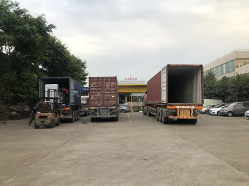
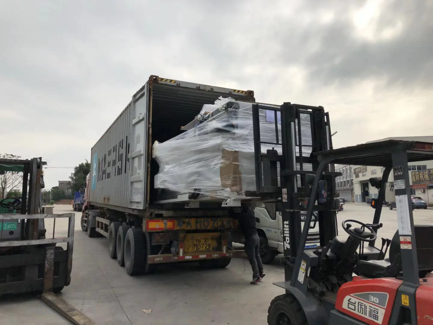
Shipment of CNC Machines
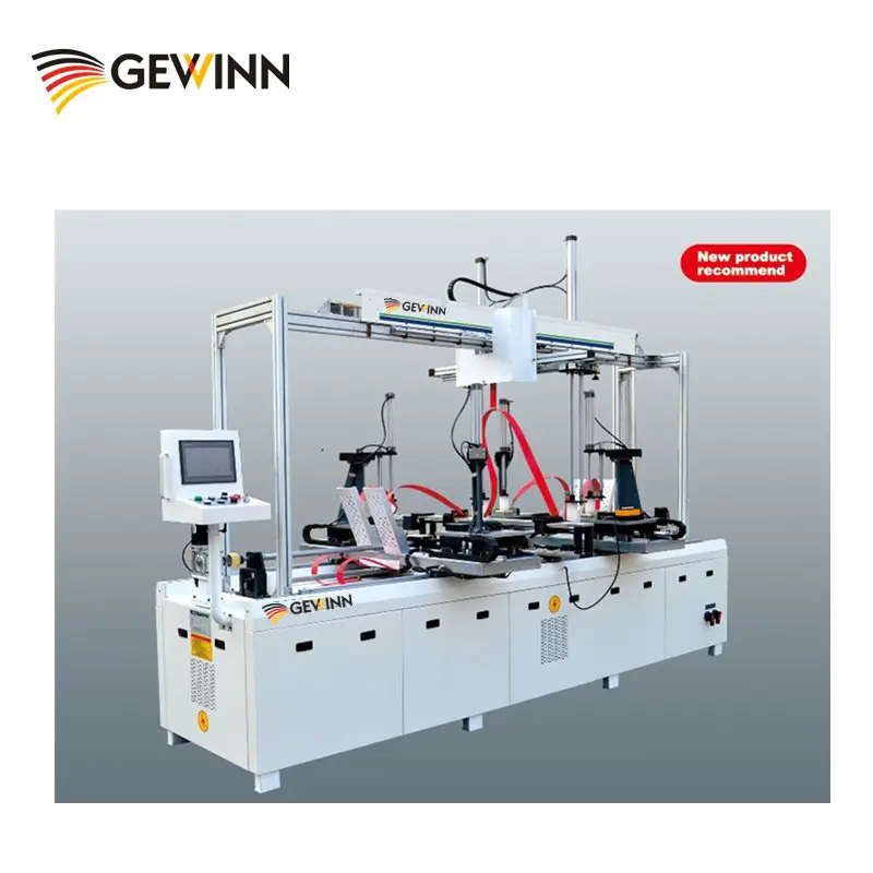
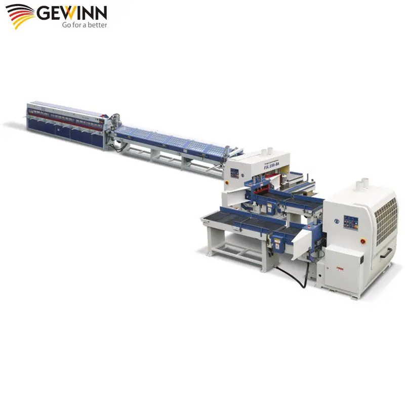
Products
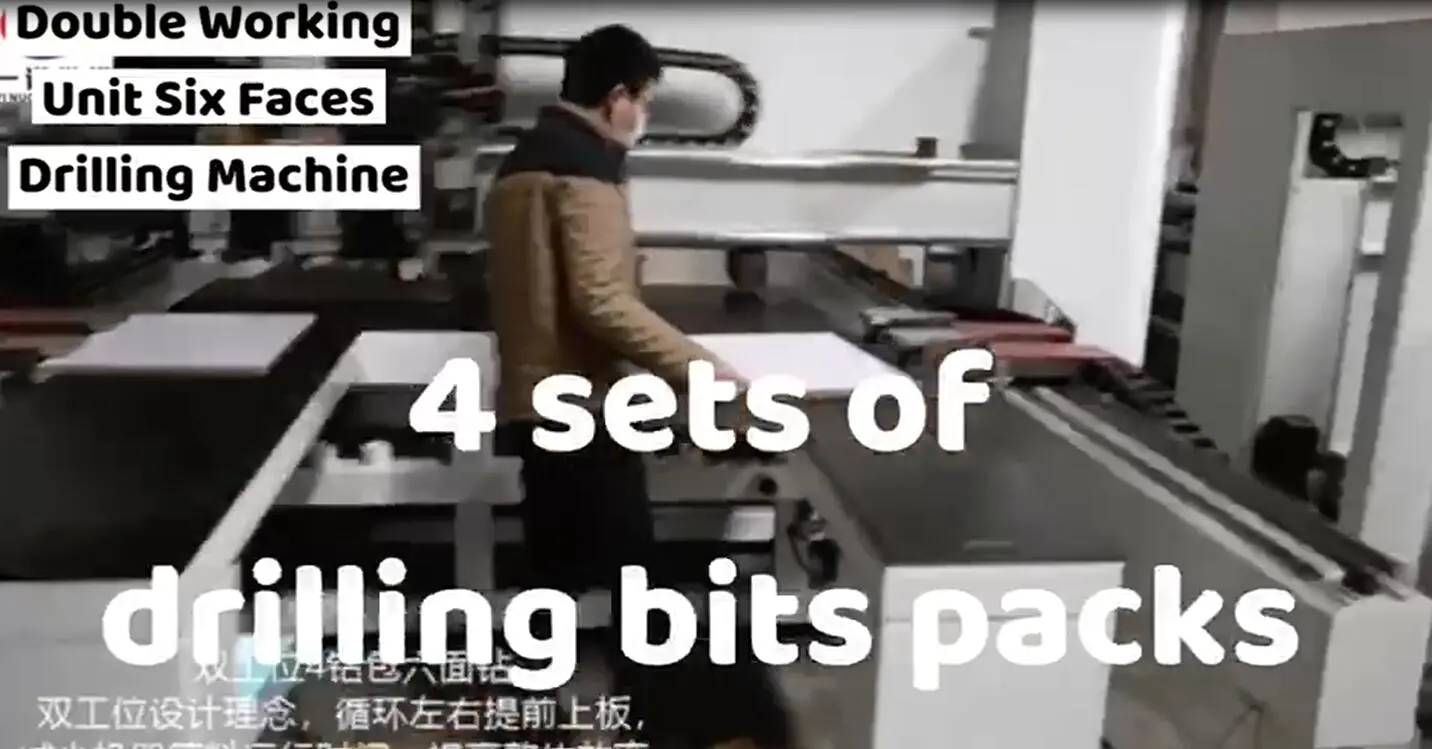
The introduction of the basic numerical control woodworking machinery structure ( 2)
by:Gewinn
2020-04-16
The day before yesterday to share the basic structure of numerical control woodworking machinery, just about four points, is not clear for you, don't know whether the four equipment you already know, few words said.
With the other seven parts for everybody!
(
1)
Dragging plate box.
Dragging plate box is the rotation of the screw or light bar to drag plate part, by the handle of outside of the transformation, the dragging plate part of lathe tool for longitudinal or transverse feeding lathe parts.
(
2)
C6140 dragging plate box with a locking mechanism and automatic stop mechanism.
It can make the light poles and in the process of cutting screw does not rotate at the same time, the longitudinal automatic feeding and screwing cannot simultaneously.
In big drag board encounter obstacles or overload, and makes the feed automatically stop, avoid damage to the parts.
(
3)
Lathe bed.
Is used to support the parts of lathe bed, such as the head of a bed box, tool box, drag plate box and such as the end of the bed are set on it.
Above the bed there are two precise guide rail, dragging plate and the end of the bed can move along the guide rail.
Lathe bed also is equipped with electric motor, electric control box, cooling pump and so on.
In order to guarantee the machining quality, lathe bed should be rigid and not easy deformation, easy chip removal, resistant to vibration.
(
4)
Light poles and screw.
Light poles are dragged the motion of the tool box to crate, make the dragging plate and turning in a certain speed mobile lathe parts.
Screw is used for thread cutting, make the dragging plate and the tool moving at a speed of lathe parts as required.
(
5)
Dragging plate.
Lathe in the dragging plate is divided into big drag board, dragging plate and small apron.
Big drag board used for longitudinal cutting long workpiece;
The dragging plate used in the horizontal turning workpiece;
Small drag board used for longitudinal cutting shorter work-piece or Angle.
Big drag board directly on the lathe bed guide rail, dragging plate box installed in the big drag board on the front of the bottom plane.
Big drag board can use manual or automatic feeding impetus for longitudinal motion.
Dragging plate through dovetail slot and wedge iron installed on the big board, can be used on the big drag board manual or automatic transverse feeding.
Small drag plate through dovetail slot and wedge in the iron and dragging plate connection.
Rely on manual, small drag plate can make the longitudinal feed movement along the dovetail guideway, short but turning parts, mobile range for lOOmm manually, by making a small drag board a relative to the center of spindle deflection Angle, but turning taper parts, the maximum rotation Angle for 45 mm.
。
(
6)
The tool carrier.
Head to the clamping tool, the installation on the small drag board at the center of the shaft.
In four kinds of cutting tool, can be mounted to the rest of the turning tool bearing surface away from the center distance of 25 mm.
When loosened by rotating the handle counterclockwise relaxation tool post, clamping tool, can handle clockwise.
(
7)
The end of the bed.
The end of the bed to a long workpiece, be installed in the rear of the lathe, it can be installed thimble, all kinds of cutting tools, such as drill, reamer, die, tap, etc.
Taper hole in the tail of the plunger sleeve is Morse taper 4, the longitudinal movement of 260 mm, lateral mobile + 15 ram.
When processing a long cone, can use the automatic feeding turning.
(
8)
Power and lubrication system.
5 kw, installed at the back of the bed.
125 kw, work with cooling pump.
In order to guarantee the normal operation of the lathe, reduce wear, all friction parts on the lathe to often come on.
(
9)
Rest and follow rest.
Rest and follow rest all belong to the lathe accessories, generally used in machining a slender shaft.
Center frame installed on the lathe bed guide rail, the car, slender shaft can be used to support the workpiece.
Processed parts through the rest of the three adjustable radial support claws, cutting can be improved when the rigidity of the system.
Specific part of the introduction of the basic numerical control woodworking machinery structure explain for everybody finished, we hope to bring you help, hope more friends know about it, if you have any questions or ideas can message small make up, small make up for your professional answer!
Custom message
Related Products