 Indonesia
 Deutsch
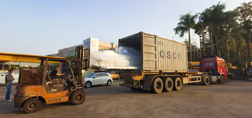
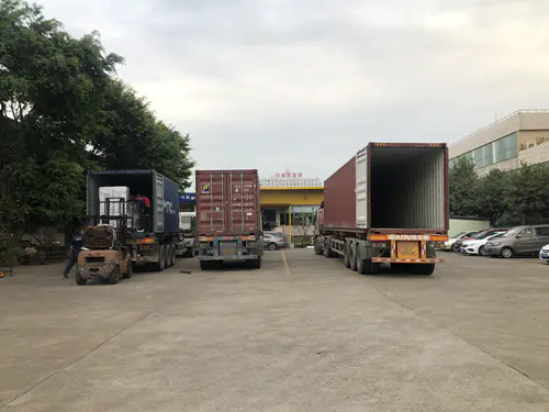
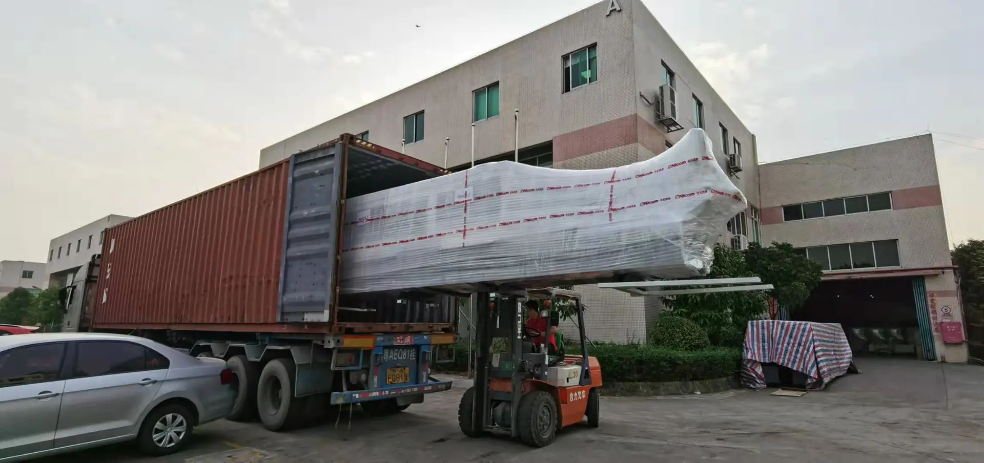
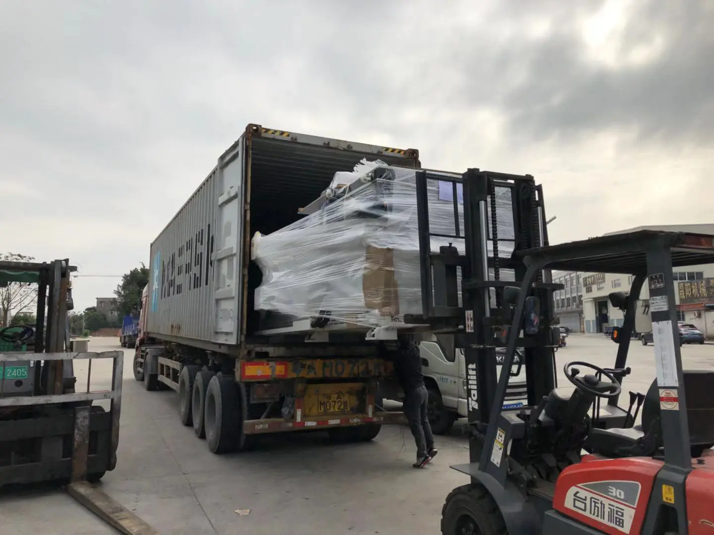
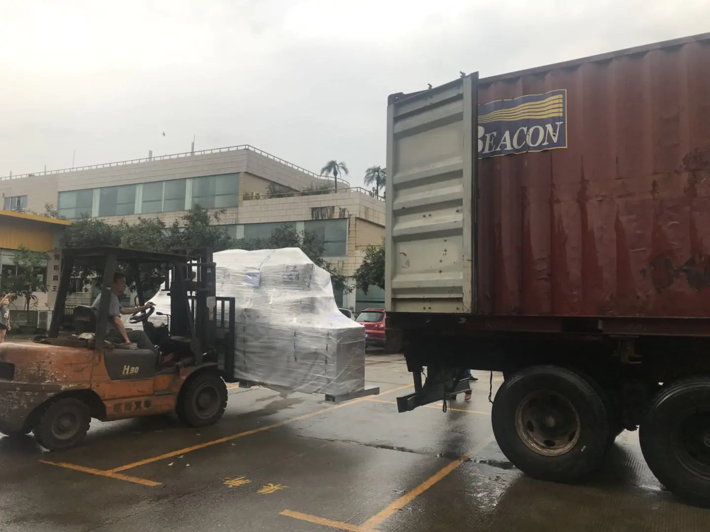
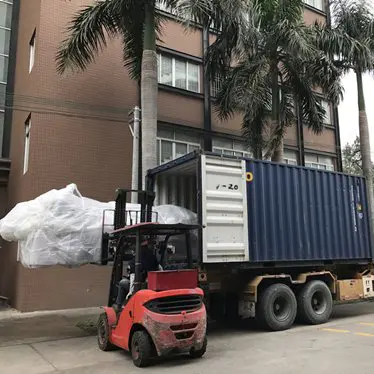
Shipment of CNC Machines
Products
turn a 2d image into a 3d model
by:Gewinn
2020-06-07
Want to turn a 2D image into a 3D model?
This Instructure will show you how to use the free script and Fusion 360. Fusion 360 (Mac / Windows)
As far as 3D software is concerned, Fusion 360 is almost everything I use now.
Fully open: Fusion 360 is an Autodesk product and the structures are Autodesk, so it seems to be a biased option.
That\'s not the case, and that\'s why: I \'ve been doing 3D modeling for 13 years and I can honestly tell you that this project is perfect for the work I do: furniture, toys, machines, household products, etc.
Laser cutting, in particular, makes digital manufacturing a breeze.
There are many other programs that can be used to produce the same results if you are happy with something else (
Especially if you have already paid for it)
There is no reason why you will not stick to it.
But if you don\'t spend any money or invest time on another project, trust me when I say you won\'t regret your use of Fusion 360.
If you haven\'t already, go to the tools and materials class in the CNC class and follow the instructions there to download and install Fusion for free as an amateur/student/educator.
Fusion 360 has a great Youtube channel with lots of useful videos.
If you\'re the kind of person who likes to learn software by browsing every feature that software can perform, this channel is a great start.
The overview here should allow you to adapt well to the interface and give you an idea of how the program works.
But before we enter a complete
Mature 3D model, I will go through the interface quickly.
PRO tip: use 3-button mouse!
This is much easier than using a trackpad.
There are three ways to manipulate the design view: the navigation bar is located at the bottom of the canvas.
It provides access to navigation commands.
Menu display settings and layout grid options on the right side control.
To start the navigation command, click the button on the navigation bar.
For example, the navigation command displays a set of commands that enable you to specify the desired visual style, visibility of the object, or camera settings.
Allows you to specify the grid and snapshot commands for increments, grid settings, and Display/hide layout grids.
ViewportsViewports is the window that displays the design.
You can display up to four viewport in the canvas at the same time.
Displaying multiple viewport allows you to work in one view and to see changes in the position of other cameras.
Rotate the camera using ViewCube.
Drag the ViewCube to perform a free track.
Click on the face and corner of the cube to access the standard orthogonal view and isometric view.
Mouse: zoom in/out, Pan views, and surround views with mouse shortcuts.
Trackpad: If you have a Mac with a touchpad or an Apple Magic Mouse, you can use more
Navigation view with touch gesture.
\"Script\" is an abbreviation for some code, you can insert the program and give it a new tool that is not included by the software developer.
There are dozens of scripts that will allow you to do something really great.
To convert a 2D bitmap image to a 3D surface for CNC milling, we will use the image-2-Surface (
Update 03/2018)
The script written by Hans ner
The script is simple.
All it does is translate the value (
Light or dark)
The height of the bitmap image to the point on the mesh surface.
The white part of the image is the highest point and the black part is the lowest point.
This script can handle any photo, but I found it would be better to use a grayscale image because it\'s easier to predict how it looks in 3D.
First, download the Zip file of the attached belo and decompress it to the location of your choice.
I would suggest keeping it somewhere other than the download folder or any other folder that is cleaned regularly.
To load the script in Fusion, perform the following steps: After opening Fusion, I save the unnamed file with the new name.
Saved my file and set the workspace to MODEL, I will go to ADD-
INS> scripts and addIns. . .
I select Image2Surface from the list and click Run \".
After you select the image, click OK to get the Image2Surface script dialog box.
Below is a breakdown of the settings and what they mean.
There are a lot of technical terms here that we won\'t talk about, but I find a good place to start learning about this kind of thing is to play with the settings and see what happens.
The settings shown in the screenshot below seem to produce the best results.
Depending on the content of the image, you may need to reverse the image.
When your settings are dialed, click OK and the script will generate the surface.
Important: The Export format must be set to OBJ so that the surface can be used for CNC work later.
Does Fusion freeze or crash when you try to run the script?
Your image may be too big.
It should not be a problem to stay below 300X300 pixels.
The smaller the image, the faster it will be processed.
If the script does not run as described even if you follow the instructions, I suggest you look at this thread in the Autodesk Knowledge Base: when the script is not working, this is because it is not installed properly.
The surface created by the script is a polygon mesh surface.
This type of surface consists of faces with edges and points.
If enlarged, you will see a surface without bending.
This geometry cannot be used to make g-
So we need to convert it to T-Flower line geometry. A t-
Spline is a surface geometry that deals with control points that affect flexible surfaces.
You need a T-
To create a CNC toolpath, click the Create> Create form tool in the menu.
This tool brings you into the engraving work area.
Next, click utilities> convert, and then select the mesh body in the selection filter.
Now click the mesh surface created by the script, and then click OK \".
Now it\'s time to wait patiently for the program to finish converting the surface to T-Spline body-
It may take a few minutes.
Click finish form and Fusion returns to the model workspace.
To better visualize what you\'re going to cut off on CNC, it\'s a good idea to create a physical form.
First, select the surface in the Bodies folder in the browser on the left-
Hand side of the screen. Then Right-
Click anywhere on the screen and select move from the menu \".
Look at the surface from the side and rotate 90 ° to make the top of the surface face up.
The size of the surface is based entirely on the original bitmap image, so now you need to scale it to fit the actual size of the part you want to crop.
To do this, make sure you select body in your browser and go to modify> zoom in the menu \".
Click point and select the model origin.
Note: In order to view Origin, you may need to open it in your browser.
Observe the surface from the top view and change the scale factor to make the surface fit the size of the part you want to crop.
I\'m going to use a piece of 3 \"x 3\" wood, so I\'m looking for a scale factor that will give me a surface that is slightly larger than 3 \"x 3.
I can see how big it is on the layout grid.
Now that the surface is in place, create a box to represent the material to be cropped.
I am using 3 \"x 3\" X.
76 \"square, so I go to create> box and click model origin as my starting point.
The Box command requires width, depth, and height, which you can enter by typing numbers and pressing Tab.
I can see that the surface to be cut is actually higher than the material to be cut, so I don\'t need to shrink the surface on the Y dimension.
I use the zoom tool again and change the zoom type to uneven.
This option will allow you to scale independently in any dimension.
For Y distance, choose a number that gives you some breathing space to fit the surface inside the block.
To close the surface to the top of the block, move to the right
Click> to move the surface up in the Y direction so that it is just below the top of the block.
In case both the block and the surface are in place, go to modify> Replace surface \".
Like other tools in Fusion, it will tell you what it needs to do.
First, select the source face, in which case the source face is the top surface of the block.
Then, click Select under target face, and then select the surface you just converted from the original mesh.
Click OK and then close the original body in your browser, and you will see the finished surface you will make on your CNC.
If you give it a try, please post your results here!
Custom message
Related Products